The international standard for low voltage switchboard arrangements, IEC 61439 'Low-voltage switchgear and control gear assemblies' sets out criteria for the internal subdivision of the busbars, functional units and external cable terminals within switchgear assemblies. These subdivisions known as ‘Forms of Separation’, can be achieved using metallic or non-metallic physical barriers or insulation.
IEC 61439 outlines 4 main forms of assembly separation;
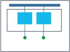
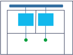
Form 1 - No segregation between busbar, terminals and functional units
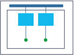
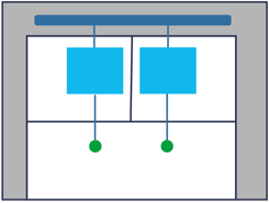
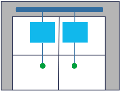
Form 2 - Functional units are separated from the busbar
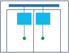
Form 3 - Busbar is separated from the functional units and the functional units are separated from each other
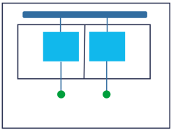
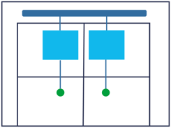
Form 4 - Busbars are segregated from the functional units and terminals. Functional units are segregated from each other.
The primary function of switchgear assembly separation is to protect the installer or operator from any electrical risk. Assembly separation facilitates safe access for personnel by ensuring the following;
- Protection against contact with live components belonging to the adjacent functional units. The degree of protection must be at least IPXXB
- Protection against solid foreign bodies being passed from one unit of an assembly to an adjacent unit. The degree of protection shall be at least IP2X.
- Limited risk of starting or propagating an internal arc.
In order to verify the separation of a switchgear assembly the appropriate IP test must be conducted inline with BS EN 60529
Choosing a Form of Separation
Whilst the safety benefits achieved through switchgear assembly separation are apparent, the benefits or drawbacks of any given form are not defined. The form chosen will be subject to agreement between the manufacturer and end user and should only be determined once the project requirements have been fully assessed. Key points to consider are as follows;
- The consequences of isolating the assembly
- Nature of task to be performed and the access required. i.e. is access to functional units needed whilst adjacent parts are live?
- Competence of person undertaking work whilst the remainder of the assembly is energized.
- Usually the higher the form of separation, the bigger the unit will be. Partitions take up additional space and can restrict airflow, warranting larger components to achieve required circuit ratings.
- The higher the form of separation, the more barriers and partitions that will be required. The extra materials and labor will increase the cost of construction.
- Is there a danger of small components falling from one compartment to another causing a hazard?
- Can temporary barriers be effectively used during periods of maintenance to supplement the protection provided by separation.
- The additional safety that can be provided using Personal Protective Equipment.
Forms of Separation in Detail
Form 1
No internal separation of the busbars, functional units or cable terminals from each other. Suitable for small low power switchboards.

Form 2
Functional units are separated from the busbars
Form 2a
External cable terminals are not separated from the busbar
External cable terminals are separated from the busbar.
Busbar separation is achieved by insulated coverings – sleeving, wrapping or coating
As form 2b type 1
Busbar separation is achieved by partitions and barriers.
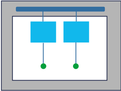
Internal separation of the busbar from the functional units and the functional units from each other via cubicles. External cable terminals are separated from their respective functional units but not from each other.
Form 3a
Terminals for external cabling are not separated from busbars
Terminals for external conductors are separated from the respective functional unit and the busbars.
Terminals are not separated from each other
Busbar separation is achieved by insulated coverings sleeving, wrapping or coating
As form 3b type 1
Busbar separation is achieved by partitions and barriers.
Form 4
Form 4 is the highest form rating. Busbars are segregated from the functional units and terminals for external cabling. Functional units are segregated from each other.
Form 4a Type 1
The terminals for external cabling are in the same compartment as the associated functional unit but segregated from terminals for other functional units
Busbar separation is achieved by insulated coverings sleeving, wrapping or coating
As form 4a type 1
Busbar separation is achieved by partitions and barriers.
Type 3 requires individual, integral cable glanding facilities to be provided for each circuit.

Terminals for external cabling are not in the same compartment as the associated functional unit.
Busbar, functional units and terminals are all fully segregated from each other
Busbar separation is achieved by insulated coverings sleeving, wrapping or coating
As form 4b type 4
Type 5 requires busbar separation by partitions and barriers with outgoing terminals separated by insulated coverings.
Type 6 requires busbars and terminals are separated by partitions and barriers
Type 7 requires Individual, integral cable glanding facilities to be provided for each circuit. Busbars and extended terminals are separated by partitions and barriers
E+I Engineering’s innovative UL switchboard design is constructed from our IEC 60349-1 product that has been tested and approved to meet UL891, UL1558 and CSA standards. The fully flexible and modular system can be constructed with separation up to form 4 type 7, adding a new dimension of operator safety and equipment protection to ANSI switchgear assemblies.
In house metalwork fabrication and paintwork facilities ensure that E+I Engineering can deliver an on-time solution for any specification.